What is a Layer 3 MPLS GRE VPN and why to use it?
The MPLS VPN L3VPN over GRE feature provides a mechanism for tunneling Multiprotocol Label Switching (MPLS) packets over non-MPLS networks. This feature allows you to create a generic routing encapsulation (GRE) tunnel across a non-MPLS network. The MPLS packets are encapsulated within the GRE tunnel packets, and the encapsulated packets traverse the non-MPLS network through the GRE tunnel. When GRE tunnel packets are received at the other side of the non-MPLS network, the GRE tunnel packet header is removed and the inner MPLS packet is forwarded to its final destination.
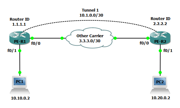
In the example below we will configure two MPLS service provider routers (PEs) and one VRF for Customer1 at both sites. The service provider MPLS network will run a basic OSPF configuration and all customer routers will participate in BGP to reach their other sites. Both customer 1 must be provisioned a VRF instance to facilitate a virtual private network across the MPLS cloud.

Steps to configure a Layer 3 MPLS GRE VPN
PE-R1(config)#interface Loopback0
PE-R1(config-if)#ip address 1.1.1.1 255.255.255.255
!
PE-R1(config)#interface FastEthernet0/0
PE-R1(config-if)#ip address 3.3.3.1 255.255.255.252
!
PE-R1(config)#router ospf 101
PE-R1(config-router)#router-id 1.1.1.1
PE-R1(config-router)#network 1.1.1.1 0.0.0.0 area 0
PE-R1(config-router)#network 10.1.0.0 0.0.0.3 area 0
PE-R2(config)#interface Loopback0
PE-R2(config-if)#ip address 2.2.2.2 255.255.255.255
!
PE-R2(config)#interface FastEthernet0/0
PE-R2(config-if)#ip address 3.3.3.2 255.255.255.252
!
PE-R2(config)#router ospf 101
PE-R2(config-router)#router-id 2.2.2.2
PE-R2(config-router)#network 2.2.2.2 0.0.0.0 area 0
PE-R2(config-router)#network 10.1.0.0 0.0.0.3 area 0
Step 2: Forcibly change the LDP router id on PE-R1 and PE-R2.
PE-R1(config)#mpls ldp router-id Loopback0 force
PE-R2(config)#mpls ldp router-id Loopback0 force
Step 3: Configure vrf vpn1 for Customer 1 on PE-R1 and PE-R2. We will also enable the VRF on the applicable interfaces and configure an IP address on the interfaces as well.
PE-R1(config)#ip vrf vpn1
PE-R1(config-vrf)#rd 65000:101
PE-R1(config-vrf)#route-target export 65000:101
PE-R1(config-vrf)#route-target import 65000:101
!
PE-R1(config)#interface FastEthernet0/1
PE-R1(config-if)#ip vrf forwarding vpn1
PE-R1(config-if)#ip address 10.10.0.1 255.255.255.0
PE-R2(config)#ip vrf vpn1
PE-R2(config-vrf)#rd 65000:101
PE-R2(config-vrf)#route-target export 65000:101
PE-R2(config-vrf)#route-target import 65000:101
!
PE-R2(config)#interface FastEthernet0/1
PE-R2(config-if)#ip vrf forwarding vpn1
PE-R2(config-if)#ip address 10.20.0.1 255.255.255.0
Step 4: Configure a tunnel interface on both PE-R1 and PE-R2.
PE-R1(config)#interface Tunnel1
PE-R1(config-if)#ip address 10.1.0.1 255.255.255.252
PE-R1(config-if)#mpls ip
PE-R1(config-if)#tunnel source 3.3.3.1
PE-R1(config-if)#tunnel destination 3.3.3.2
PE-R2(config)#interface Tunnel1
PE-R2(config-if)#ip address 10.1.0.2 255.255.255.252
PE-R2(config-if)#mpls ip
PE-R2(config-if)#tunnel source 3.3.3.2
PE-R2(config-if)#tunnel destination 3.3.3.1
Step 5: Next configure a BGP process on PE-R1 and PE-R2 to facilitate advertisements of customer networks over the MPLS network.
PE-R1(config-router)#router bgp 65000
PE-R1(config-router)#bgp log-neighbor-changes
PE-R1(config-router)#neighbor 2.2.2.2 remote-as 65000
PE-R1(config-router)#neighbor 2.2.2.2 update-source Loopback0
!
PE-R1(config-router)#address-family vpnv4
PE-R1(config-router-af)#neighbor 2.2.2.2 activate
PE-R1(config-router-af)#neighbor 2.2.2.2 send-community extended
PE-R1(config-router-af)#exit-address-family
!
PE-R1(config-router)#address-family ipv4 vrf vpn1
PE-R1(config-router-af)#redistribute connected
PE-R1(config-router-af)#neighbor 10.1.0.2 remote-as 65000
PE-R1(config-router-af)#neighbor 10.1.0.2 activate
PE-R1(config-router-af)#exit-address-family
PE-R2(config-router)#router bgp 65000
PE-R2(config-router)#bgp log-neighbor-changes
PE-R2(config-router)#neighbor 1.1.1.1 remote-as 65000
PE-R2(config-router)#neighbor 1.1.1.1 update-source Loopback0
!
PE-R2(config-router)#address-family vpnv4
PE-R2(config-router-af)#neighbor 1.1.1.1 activate
PE-R2(config-router-af)#neighbor 1.1.1.1 send-community extended
PE-R2(config-router-af)#exit-address-family
!
PE-R2(config-router)#address-family ipv4 vrf vpn1
PE-R2(config-router-af)#redistribute connected
PE-R2(config-router-af)#neighbor 10.1.0.1 remote-as 65000
PE-R2(config-router-af)#neighbor 10.1.0.1 activate
PE-R2(config-router-af)#exit-address-family
Verify the configuration
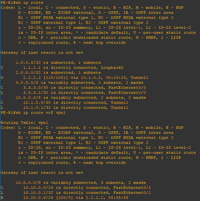
Now that the configuration is finished lets verify our neighbors and routes. Using the show mpls forwarding-table, show ip bgp vpnv4 all, show ip route, show ip bgp neighbors commands you can verify the MPLS deployment, BGP routes distributed and to which VRF they belong. Use the ping command to verify connectivity from PC1 to PC2.

